I’ve been poking around at my Winegard Trav’ler antennas a bit and have some additional info beyond what’s on my Github and prior posts. I’ll post some of it here (this was originally on my Discord).
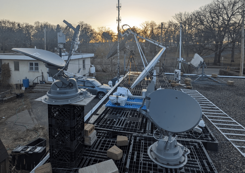
These are the “regular size” satellite TV dishes found on RVs that have a motorized turret to point them, and stow them flat on the roof. They look like a household dish, not the smaller domes of the Carryout series. The Backyard Scientist also used one as a laser turret in one of his videos. You can often find these for sale on Craigslist / Facebook Marketplace in the $200-$300 range, but there’s not actually a lot of demand for used ones. If they’ve been listed a while you can try offering them less. I have picked up two for free and one for $50.
I’ve run into a few different models and firmware revisions on the Trav’ler series. The ones I’ve seen all have the brain / control board (AKA “Outdoor Unit” or ODU) under the motor turret. The small interface box that sits inside an RV is the Indoor Unit or IDU, and generally seems to just be a dumb display / serial interface / power injector. The Pro model has a little more going on with the IDU (ethernet, USB terminal, and onboard microcontroller that you can talk to), but to run the Pro I’ve just consoled through the IDU and into the ODU board. I didn’t like the Pro as much since the elevation seemed limited to about 75 degrees. The slightly older LG2112 model seems to have more range of motion. I’ve found that even LG2112 models from similar years can have different firmware (called HAL) versions with different commands. So far I have encountered HAL v0.0 and HAL v2.05, and had to write slightly different code for each of them.
Generally when they power on there’s a boot sequence, and if the dish has been stowed flat it will unfold. Then there’s a calibration dance to find the motion limits, then a search pattern for whatever TV satellite it’s programmed for. I usually let it do the calibration and then kill the search process in the firmware’s task manager (the timing and process for that is a little different depending on the firmware). I could potentially just leave it powered to avoid the dance every time, but I don’t like leaving hacked-together gear plugged in all the time just in case something goes wrong. I never stow mine since I replace the LNB with other feeds which would get crushed by the stowing process.
My code to use these as a general-purpose azimuth/elevation rotor is on Github at the following links. Each has some additional details in the readme:
Trav’ler LG2112 with HAL version was 0.0: https://github.com/saveitforparts/Travler_Rotor
Trav’ler Pro: https://github.com/saveitforparts/Travler-Pro-Rotor
LG2112 with HAL 2.05: https://github.com/saveitforparts/Trav-ler-Rotor-For-HAL-2.05
If you find a Trav’ler that has been removed from an RV by an amateur, it may have cut cables, missing cables, missing IDU and/or power supply. These can be cheaper, or can be a good way to negotiate the price down!
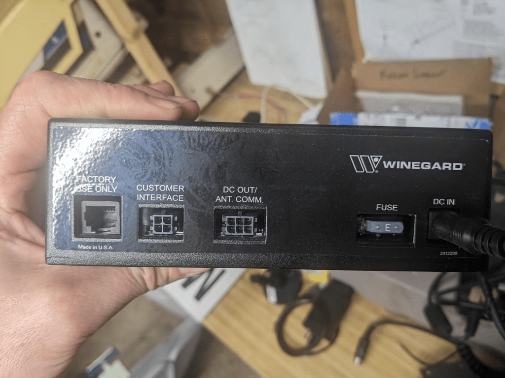
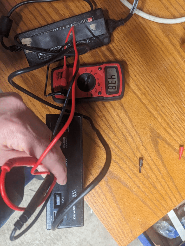
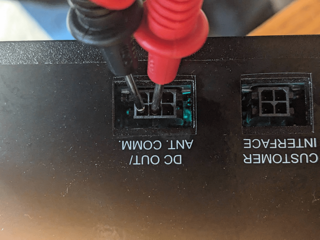
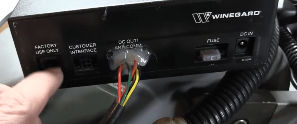
The “official” power supply for the brain/motors is 48V DC. If you’re feeding it 13v/18v through the Coax cable that will just run the LNB and maybe the TV receiver subsystem on the board. On my first one I’m actually using a 52V DC power brick since that’s the closest thing I could find. I tried powering the other one with the real power supply and got about 44v out of the top right pins of the 6-pin port. It would only give me that for a few seconds until it decided there was no antenna and threw an error. When looking at the back of the IDU, the top right pin is – and top center is +. On the one I have wired up, the wires would be yellow for + and orange for – (I didn’t have the actual connector end so I had to just hot glue them in there based on an image search).
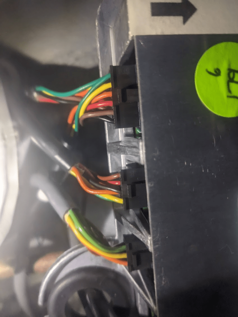
It looks like the 6-pin connector on the ODU brain is the same (bottom plug in the next photo). Wire colors there are green, yellow, orange on the top row by the clip, then I think red, brown, black on the bottom (it’s kind of hard to see without taking the plastic shield off which is a bit of a hassle). That’s the same pattern as the IDU.
If you need a new IDU, power supply, and/or cable, check eBay. Sometimes (as of 2025) they show up in the $50-$75 range.
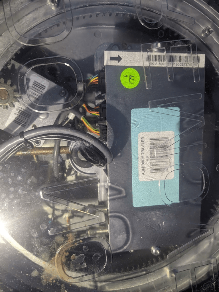
The bottom of the ODU / Turret generally has a clear plastic cover where you can see the guts. This can be removed, although it should be replaced to keep things waterproof. The ODU box has connections for the motors and IDU as well as coax connectors for the LNB. A subsystem on the ODU receives satellite TV signals and looks for the desired transponder for Dish network or DirecTV etc. There should also be another RJ-25 “phone jack” on the ODU, as there is on the IDU. This is the serial (RS-485) interface for computer control.
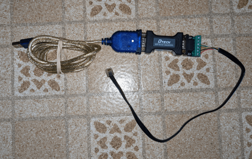
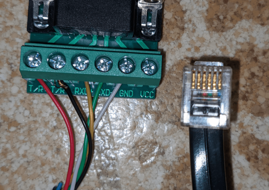
A mentioned in prior posts, interfacing with the Trav’ler serial port requires an RS-485 cable and 6-pin phone connector (RJ-25). Note that this is larger than a “normal” phone cable (although who’s seen one of those in the last 20 years?). This adapter also works on the Winegard Carryout series and possibly other antennas.
I have included a photo of the USB adapter chain that I use. It includes a USB-to-Serial cable, a DTECH RS232-to-RS485 converter, and an RJ-25 jack wired as follows (looking at the bottom of the phone connector with the tip up):
Pin 1: GND
Pin 2: T/R-
Pin 3: T/R+
Pin 4: RXD-
Pin 5: RXD+
Pin 6: Not used

I’ve been following these videos on YouTube with great interest. This is a very interesting subject Gabe, and I really like the way you go about getting the info to us. You pitch it at a level that is a good mix of basic and technical, and that suits me just fine. Keep up the good work pal, and stay safe 👍